Invented by Benjamin Weiss, Jon Turkington, Adam Crouch, Richard S. Majka, Atul Singh, Walgreen Co
Traditionally, the prescription process involves handwritten prescriptions that are prone to errors, illegibility, and potential misinterpretation. This can lead to medication errors, adverse drug reactions, and patient harm. The System and Method for a New Prescription Scan offers a digital alternative to this outdated practice.
The system utilizes advanced scanning technology to capture and digitize prescriptions, eliminating the need for manual data entry. This not only saves time but also reduces the risk of transcription errors. The scanned prescriptions are then securely stored in a centralized database, accessible to healthcare professionals, pharmacists, and patients, ensuring accurate and efficient medication management.
One of the key advantages of this system is its ability to flag potential drug interactions and allergies. By scanning the prescription, the system can cross-reference the prescribed medication with a comprehensive database of drug interactions and patient allergies. This real-time analysis helps healthcare professionals make informed decisions and prevent adverse drug events.
Furthermore, the System and Method for a New Prescription Scan offers convenience for patients. With the integration of mobile applications, patients can easily upload their prescriptions, eliminating the need for physical visits to healthcare facilities. This not only saves time and effort but also reduces the risk of lost or misplaced prescriptions.
The market for this innovative solution is expected to witness significant growth in the coming years. The increasing adoption of electronic health records (EHRs) and the push for interoperability in healthcare systems are driving the demand for digital prescription solutions. Additionally, the COVID-19 pandemic has accelerated the need for contactless and remote healthcare services, further fueling the market growth.
Pharmaceutical companies, healthcare providers, and pharmacies are recognizing the benefits of implementing the System and Method for a New Prescription Scan. By digitizing the prescription process, they can improve operational efficiency, reduce costs associated with medication errors, and enhance patient satisfaction.
In conclusion, the market for System and Method for a New Prescription Scan is witnessing rapid growth as the healthcare industry embraces digital solutions. This innovative system offers numerous benefits, including improved patient safety, enhanced efficiency, and convenience. With the increasing adoption of electronic health records and the demand for contactless healthcare services, the market for this solution is expected to expand further in the coming years.


The Walgreen Co invention works as follows
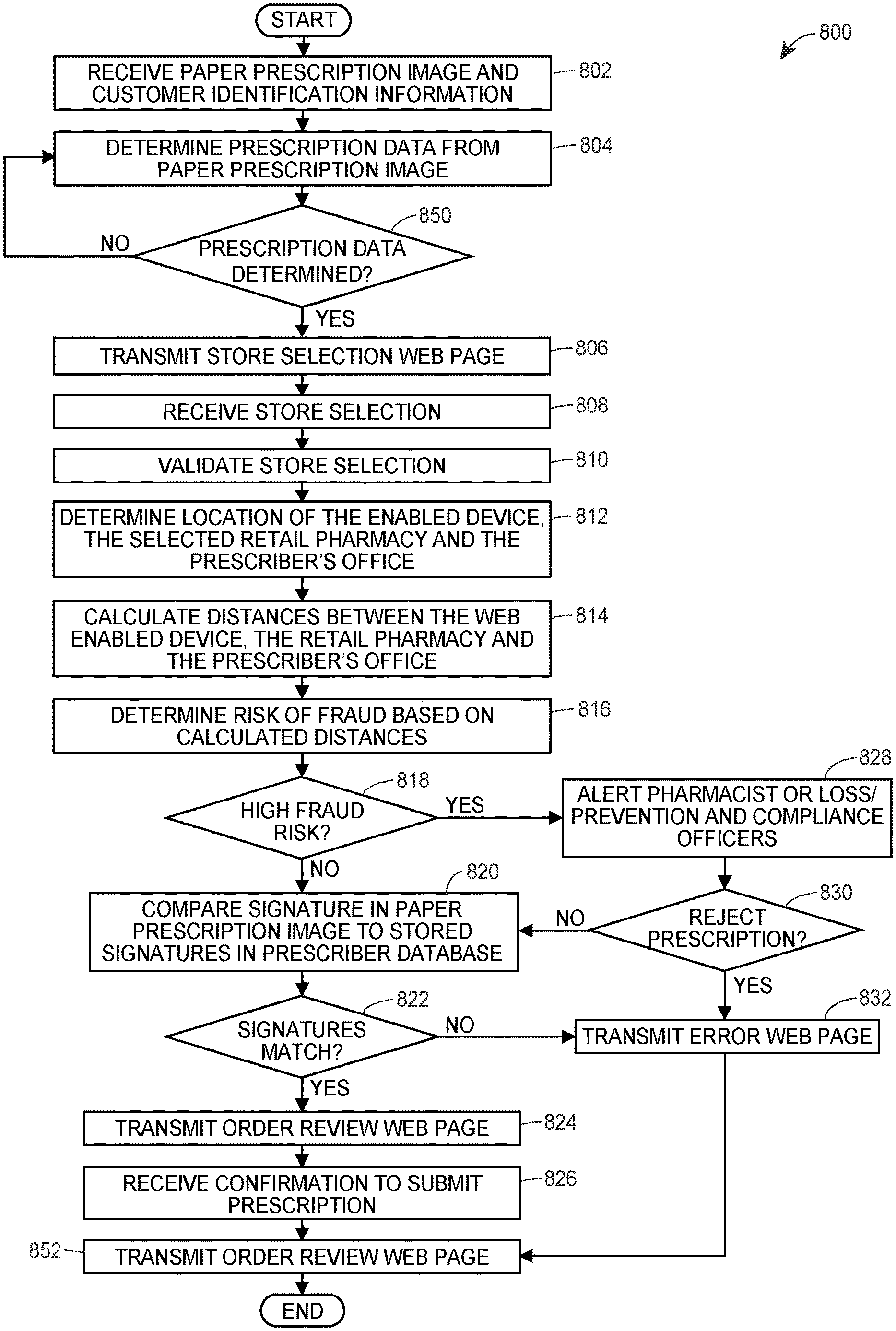
A method and a system may provide an interface for ordering prescriptions that allows customers to quickly and easily order new medications from a remote computer or mobile device. A customer submits a new image of a paper prescription that contains the prescription data to a pharmacy for the new prescription order. A server receives the new paper prescription and determines a default pick-up store and default pickup time. The server will also check if there is a risk of fraud by comparing the signature on the new paper order to the stored signatures for the prescriber and comparing the distances between the location of the web-enabled devices, the pharmacy and the prescriber. The system can be accessed via a set of web pages or an application.


Background for System and Method for a New Prescription Scan
In the past, patients (or customers) who wanted to order new prescription medications had to visit a local pharmacy and drop off a paper prescription. Some patients could order a new prescription by mail, phone, or facsimile. The pharmacy would then call the prescriber and confirm the legal prescription.
In any case, the current systems require that a patient who wants to order a paper prescription call, visit, send a fax, or mail it to the pharmacy. All of these processes can be time-consuming. The customer may have to drop off the paper prescription at the pharmacy, and then wait for 20-30 minutes until the medication is ready. Many pharmacists must also examine a paper prescription in order to determine if it is fraudulent. For example, if the signature of the prescribing doctor was forged or if the prescriber does not have a license, etc. This can take a lot of time, and pharmacists may also make mistakes in judgement. They might fill fraudulent prescriptions but refuse to fill legitimate ones.
In one embodiment, there is a method for detecting fraud in the filling of a new prescription for one or more prescription drugs. The method comprises receiving, via a network, from a web enabled device of a client, an image a of new paper prescribed for the customer. It then determines a pharmacy to fill the new prescription order, and based on that image, determining prescription data, which includes identification of the prescriber who printed or wrote the new prescription. The method also includes determining the location and prescriber of a web-enabled tablet, pharmacy and prescriber. It then determines the risk of fraud by calculating a score based on a number of distances. When the risk of fraud is not greater than a threshold, the method also includes sending, via the internet, information that will be displayed on an order review page of the web enabled device and receiving confirmation from the web enabled device via the Internet to submit a new prescription order.
In another embodiment, there is provided a system to detect fraud when a new order for prescription medication is filled. The system comprises a communication network and one or multiple server computers that are communicatively connected to the network. One or more server computers are configured to receive an image of a paper prescription from a web enabled device that is communicatively connected to the network. They can then determine the pharmacy to which a new order of prescriptions corresponding to this new paper prescribing will be filled, and they can determine prescription data using the image. The prescription data may include the identification of the prescriber who printed or wrote the new prescription. The server computer is also configured to determine the location and prescriber of the web enabled device and to assign weights to distances between these locations. When the risk of fraud is not greater than a threshold, at least one server computer can transmit information from the server to the web enabled device via the network and receive confirmation from the web enabled device via the net to submit a new prescription order.
A new prescription order system allows the customer to scan in a paper prescription that has been handwritten or printed out by a healthcare professional (also known as a “prescriber”). The system retrieves the prescription data from the new paper prescription using a web enabled device. The customer logs into the system, launches the client application, and navigates to the image capture screen in the client application. The client application scans the paper prescription by using the image capture feature. The new prescription ordering system retrieves the prescription data automatically and lets the customer select a pharmacy, a pickup time and date, as well as a location. The system not only transmits the order to the pharmacy selected, but also performs a fraud analysis to make sure the new prescription order does not contain fraudulent information.
To perform fraud analysis, this system calculates distances between the web enabled device, the pharmacy selected and the office of prescriber that wrote or printed the paper prescription. The system compares the signature of the new prescription with the previously stored signatures of the prescriber. The system will determine a high fraud risk if the distances between a web-enabled device and the pharmacy selected, or the signatures don’t match.
FIG. 1A shows various aspects of a new exemplary architecture for implementing the prescription order system. FIG. 1A shows a block diagram for the new system of prescription orders 100. The high-level architectural design includes both software and hardware applications as well as data communication channels to communicate data between hardware and software components. The new prescription ordering system 100 can be divided roughly into front-end and back-end elements. The front-end component 102 is mainly disposed in a retail network 110 that includes one or more pharmacies 112. By way of example, the pharmacies 112 can be located in different geographic locations, such as different areas within a city, or different cities. The front-end component 102 comprises a number pharmacy workstations 128, which are local computers located in the various pharmacies 112 throughout the retail network 110. The pharmacy workstations 128, which are local computers in various pharmacies 112 across the retail network 110, execute various pharmacy management applications. The term “pharmacist” is used to refer to pharmacists, technicians and other pharmacy staff. The pharmacy workstations 128, which are not shown, allow (not shown) to access information about customers, enter paper prescriptions, and access payment and insurance information. The pharmacies 112 can be, for instance, a retail pharmacy in-store, an online pharmacy, mail-order, long-term-care pharmacy, workplace/on site pharmacy or specialty pharmacy. The retail network 110 can also include one, two or more central-filling centers 118. The central-filling facility 118 can distribute retail products or medications to the retail pharmacies 112. They may also distribute retail products or medications directly to customers. Web-enabled 206-216 devices (e.g. personal computers, smart phones and cellular phones), etc. The pharmacies 112 may be connected with a system 140 via a digital network 130.
The front-end components could be a plurality facility servers 126 located at the pharmacies 112, instead or in addition of a plurality pharmacy workstations 128, as those of ordinary skill will recognize. Each of the pharmacies 112 may include one or more facility servers 126 that may facilitate communications between the workstations 128 of the pharmacies 112 via a digital network 130, and may store information for a plurality of customers/employees/accounts/etc. Each facility is associated with a server. A local digital network (184), however, may be used to connect the facility server 126 with each of the workstations 128, as well. If not stated otherwise, all references to workstations 128 refer to facility servers 126 and vice versa. The workstations 128, and servers 126, can be used in environments other than pharmacies 112. The term “pharmacy” is used in this document. The term “pharmacy” is used herein to refer to any of these environments, e.g. call centers, kiosks and Internet interface terminals. In addition to retail pharmacies 112, etc.
The front end components 102 communicate to the back end components 104 through the digital network 130. By configuration or by restricting access, one or more front-end component 102 can be prevented from communicating with the backend components 104. Web-enabled devices (206-216) may, for example, be denied direct access to back-end components. In some embodiments the pharmacy 112 can communicate with the back end components via the network digital 130. In some embodiments, web-enabled device 206-216 and the pharmacy 112 may communicate with back-end components via the digital network 130. However, digital access rights and IP masking and other network configurations can deny access to web-enabled device 206-216.
The digital network 120 may be a proprietary or public network. It could also be a virtual network. Data communication can be carried out over the digital networks 130 using an Internet communication protocol when the digital network comprises the Internet. The back-end components include, in addition to the one or more servers (described below), a central processor system 140, which is located within a central computing facility such as the central processing facilities described, for example, in U.S. Pat. No. No. 8,175,891 entitled “DISTRIBUTED PRESCRIPTION SYSTEM?” The entire disclosure is incorporated herein by reference. The pharmacies 112 can be connected in a communicative manner to various back-end components (104), which may have one or more capabilities or functions similar to those of the central processing system. The central processing system may be comprised of one or more computer processes 162 that are adapted to and configured to run various software applications, components and the new prescription ordering system 100 in addition to software applications. The central processing system includes a database. The database 146 can be used to store information related to the new prescription ordering system 100. (e.g. patient profile data such as diagnoses, previous healthcare purchases, prescription histories, and physician profile data, including DEA numbers, previously written prescriptions and past signatures as well as office location). The central processing system may use data from the database 146 to perform various tasks and functions associated with the operation the new prescription ordering system 100.


Although FIG. The new prescription order system (100) is shown in FIG. 1A as having the central processing system 140 communicating with three pharmacies 112, along with various web-enabled device 206-216. However, it should be noted that the number of pharmacies and devices can be varied. The digital network 130, or other digital networks (not shown), may, for example, interconnect a central processing system to hundreds of pharmacies 112. It could also connect the central processing system to thousands of web-enabled 206-216 devices. This configuration, according to the example disclosed, may offer several advantages. For example, it allows for near-real-time uploads/downloads as well as periodic downloads/uploads. This allows for a primary back-up of all information generated during the new prescription process. Some pharmacies 112 store their data on the local server 126 or workstations 128, but others may use the facility server.
FIG. The central processing system 140 is also shown in 1A as a possible embodiment. The central processing system may include a controller (155), which is operatively linked to the database (146) via a link (156), connected to an I/O circuit 166. Although not shown in the diagram, other databases can be connected to the controller 155 using a known method.
The controller 155 includes the following: a program memory 162, the processor 162(which may be called a Microcontroller or a Microprocessor), the random-access memory 164 and the input/output circuit 166. All of these are connected via an address/databus 165. Although only one microprocessor is shown in the illustration, it should be noted that the controller 155 can include multiple microprocessors. The memory of the controller may also include multiple RAMs 164 and multiple program memories. The I/O block 166, although shown as one unit, may contain a variety of I/O blocks. The RAM(s), 164, and program memories 160 can be implemented, for instance, as magnetically-readable memories or optically-readable memories. “A link 135 can be used to connect the controller 150 with the digital network 130 via the I/O circuits 166.
The program memory may also include machine-readable instructions, i.e. software 171, which are executed by the processor 162. Software 171 can perform various tasks related to the operation of the pharmacy. It may be a single 171 module or a plurality 171A,171B modules. The software 171 in FIG. The software 171 is shown in FIG. 1A to include two modules, 171A, and 171B. However, the software may contain any number of modules that accomplish tasks related pharmacy operations, such as receiving prescription orders, managing workflow, etc. The central processing system implements a server app 113 to provide data to an user interface app 111 running on the workstations 128,
Now turn to FIG. The server 202 has a controller 224, just like the facility server. The controller 224, like the controllers 170 and 155, includes a RAM 230 and an I/O circuit 234. All of these components are connected via an address/databus 232. In certain embodiments, the control 224 can also include or be communicatively linked to a database or another data storage device (e.g. one or more optical storage devices, solid-state storage devices, etc.). The database 239 can include data like customer web profiles and prescriber web profile, product data and mobile device application data. It may also contain web page templates or web pages and other necessary data to interact with users through the network 130. It should be noted that, as discussed in relation to controllers 155 & 170, FIG. The controller 224 can include more than one microprocessor 228. The memory of the controller may also include multiple RAMs (RAMs) 230, and multiple program memory 226. The FIG. The I/O Circuit 234 is shown in FIG. The controller 224 can implement the RAM(s), and program memories 226, as semiconductor memories or magnetically-readable memories and/or optically-readable memories.
In addition to being able to connect through the network 130 with the web-enabled device 206-216 as shown in FIG. 1B, FIG. 1C shows that the server may be connected via the network 130 with the central processing system (140) and/or to one or more facility servers (126). The connection between the server 202 and the central processing system is described in the following paragraphs. This helps to facilitate some functionality of the new order process. The server 202 can act as an interface or routing server between a plurality of web enabled devices 206-216, and a destination, which is the central processing system. The server 202 can be configured to communicate with the central processing system and the web-enabled devices 206-216 using a variety of protocols such as packet-switched protocol, web services, APIs for web, etc. The server 202 can also convert and route data from client applications (not shown) if needed to the appropriate server. For example, the central processing system 140. The server 202 can also act as a destination server, and does not need to route data from web-enabled devices 206-216.
As shown in FIG. The RAM 230 and/or program memory 226 of FIG. 1C may be used to store different applications that will be executed by the microprocessor 228, as shown in FIG. A user-interface 236 can, for instance, provide a user’s interface to the server. This user interface could, for example allow a network administrator, to configure, troubleshoot or test different aspects of the servers operation or to access other information. A server application 238 is used to transmit data from client applications and web pages to web-enabled devices 206-16, to receive data sent back by the user to the server 202 and to forward the appropriate data to central processing system 140, and to facility servers 126. As with the software 171 in FIGS. The server application 238 can be one module or multiple modules. The server application 238 in FIG. The server application 238 can include as many modules as necessary to accomplish tasks related with the implantation of server 202. The module 238A, for example, may transmit and populate the client application data, and/or receive and evaluate user inputs to receive a request to access data, while the 238B module may communicate with the back-end components 104 in order to fulfill the data access requests.
The GPS unit 244 can use “Assisted GPS” (A-GPS), satellite GPS, or any other suitable global positioning protocol or system that locates the position of the mobile device 212. A-GPS, satellite GPS or any other global positioning system or protocol that can locate the location of the mobile device 212 is acceptable. A-GPS, for example, uses terrestrial cell phone towers, wi-fi points (e.g. wireless routers) to determine the location of mobile device 212 more accurately and quickly, while satellite GPS are generally more useful in remote areas that lack cell phones towers or wifi points. The communication unit 258 can communicate with the server via any wireless communication protocol, including a wireless telephony (e.g. GSM, CDMA or LTE). Wi-fi (802.11 standards), WiMAX, Bluetooth, etc. The image capture device may be a camera built into the mobile device or an external camera such as a Webcam that is communicatively connected to the mobile device (or any other device 206-216 that supports the web). The user-input (not shown) can include a “soft” keyboard. The user-input device (not shown) may include a?soft? keyboard displayed on the display of the mobile device, an external hardware key board communicating via wired or wireless connections (e.g. a Bluetooth keyboard), or any other appropriate user-input devices. It should be noted that, as discussed in relation to controllers 155 & 224, FIG. The controller 242 can include more than one microprocessor 248. The memory of the controller may also include multiple RAMs (RAMs) 250 and multiple Program Memories 246. The FIG. The I/O Circuit 254 is shown in FIG. The controller 242 can implement the RAM(s), 250 and program memories 246 in a variety of ways, including as magnetically-readable memories and/or optically-readable memories.
Click here to view the patent on Google Patents.


