Invented by Velibor Kilibarda, Comau LLC
Modular Vehicle Assembly System and Method refers to a manufacturing process where vehicles are built using pre-designed modules that can be easily assembled and disassembled. This method allows for greater flexibility and efficiency in production, as well as cost savings for manufacturers.
One of the key advantages of the modular assembly system is its ability to streamline the production process. By using standardized modules, automakers can reduce the time and resources required for vehicle assembly. This results in faster production cycles and increased output, allowing manufacturers to meet the growing demand for vehicles more efficiently.
Additionally, the modular assembly system enables automakers to easily adapt to changes in consumer preferences and market demands. With modular components, manufacturers can quickly introduce new features or designs without having to overhaul the entire production process. This flexibility allows for greater customization and personalization of vehicles, which is highly valued by consumers.
Moreover, the modular assembly system offers cost savings for automakers. By using standardized modules, manufacturers can take advantage of economies of scale and reduce production costs. This can result in lower prices for consumers, making vehicles more affordable and accessible to a wider range of customers.
Furthermore, the modular assembly system promotes sustainability in the automotive industry. By using modular components, manufacturers can easily disassemble vehicles at the end of their lifecycle and recycle or reuse the modules. This reduces waste and minimizes the environmental impact of vehicle production.
The market for Modular Vehicle Assembly System and Method is expected to continue growing in the coming years. The increasing demand for vehicles, coupled with the need for more efficient and sustainable manufacturing processes, is driving the adoption of this innovative approach. Additionally, advancements in technology, such as automation and robotics, are further enhancing the capabilities of modular assembly systems.
Several major automakers have already embraced the modular assembly system and have reported positive results. Companies like Volkswagen, BMW, and Ford have implemented modular production lines in their manufacturing facilities, leading to increased productivity and cost savings.
In conclusion, the market for Modular Vehicle Assembly System and Method is experiencing significant growth due to its numerous benefits for automakers. This innovative approach to vehicle manufacturing offers greater flexibility, efficiency, cost savings, and sustainability. As the demand for vehicles continues to rise, the adoption of modular assembly systems is expected to increase, further driving the growth of this market.


The Comau LLC invention works as follows
A modular vehicle-assembly system and methods to increase flexibility and adaptability in a high volume assembly facility that builds multiple vehicle models.” In one example, modular assembly equipment support pallets are used to ship to vendors to install AE equipment specific to predetermined assembly operations. These devices are then validated before being shipped to the assembly facility. The validated modular assembly equipment (AE) pallets and devices are then shipped and installed quickly at the assembly facility to support manufacturing, assembly and other operations.


Background for Modular Vehicle Assembly System and Method
Large assembly plants have been used for the traditional high-volume manufacture and assembly. Multiple assembly lines are used in these assembly plants to connect, assemble and assemble components. The manufacture and assembly process of vehicle bodies includes a skeleton made of sheet metal parts that are joined together using resistance spot welding, seam welds and brazing to create what is commonly known as ‘body-in-white’ structures. (BIW) structures.
Assembly plants are attempting to use flexible building processes to accommodate the increasing demand for vehicles. This includes alternate vehicle body models. Due to limited space and time, it is difficult for facilities to switch from one body type to another.
The design, build and installation of new assembly systems (testing and proving-out), is a time-consuming and costly endeavor, both for suppliers and OEMs (original equipment manufacturers) who are ultimately responsible for the operation of assembly facilities and production. The OEMs are under constant pressure due to the increased competition and consumer demands. They want assembly systems that are more efficient and cost-effective (higher unit or vehicle per hour throughput), and they also want them to be operational within a short time frame.
The design of an assembly line has traditionally been a multi-stage process due to the many assembly systems, components and equipment that need to be operated in a specific order to assemble a car (or another product). The final design of the equipment (for example, called “Time B”) is an example. Equipment that is dependent on a supporting structure (for example, equipment called “Time A” Equipment could not be finished until its Time A support structure was designed. After the Time A infrastructure and assembly systems have been designed, constructed and installed, it is not possible to commission or test the Time B equipment until the Time A equipment and support structure has been delivered and installed in the OEM assembly plant. OEMs often award parts of assembly line Time A equipment and Time B to multiple suppliers in order to take advantage of their expertise. In the event that a supplier is late in designing, building or installing Time A equipment, this can cause delays for Time B suppliers, resulting in a cascade of delays throughout the rest of the design and build, installation, and commissioning stages. The assembly systems and equipment should be as generic or non-model-specific as possible. These systems and equipment can be used to produce all or most variations of a vehicle or product, even if they have different features or models. “These non-model-specific systems and equipment (Time A), could be fabricated and installed, even if final decisions have not yet been made about the product that will be produced (which would affect the Time B non generic or model-specific assemblies equipment and systems).
It is also time-consuming and expensive for OEMs to switch over assembly plants or assembly lines from one vehicle model to another or to a completely different vehicle. Even moderate to simple changes to the equipment infrastructure of an assembly line can take weeks or days to complete, leading to costly production shutdowns.
Prior assembly systems used specific layouts in assembly plants to reduce the floor space needed and increase efficiency and vehicle throughput. The ComauFlex System, which is produced by the assignee of this invention, was widely used by OEMs. Details of this system can be found in U.S. Pat. No. The entire content of 8,201,723 is incorporated by reference herein and briefly discussed in the following. U.S. Pat. contains details of variations in the ComauFlex layout system. Nos. Nos. 8,869 370, 8,713,780, and U.S. Patent Application Publication (2012/0304446) all assigned to the assignee of this invention and all incorporated by reference herein. These systems reduced the need for storing components and subassemblies to be installed near the assembly line or specific assembly stations, which cluttered the floor and complicated logistics.
Prior assembly systems used modular subsystems for vehicle assembly. These provided benefits in accommodating new installations, batch and random vehicle build where different vehicle types or models could be built on the same assembly line. Prior assembly subsystems used modular robotic assembly cells or stations that could be arranged end-to-end in order to accommodate an assembly line or a series of operations. For example, each assembly station or cell included a modular, precision-manufactured to close tolerances scaffold frame structure and could be selectively equipped with the necessary number of industrial, multi-axis robots and end effectors for a specified assembly operation. The U.S. Pat. cited above contains more details. Nos. “Nos. 8,201,723 and 8,869,370, as well as U.S. Patent Application Publication No. 2012/0304446, are all incorporated by reference.
The assembly system, as a unit, continues to suffer from the complexities and limitations mentioned above, despite the many advantages and efficiencies it offers. For example, the peripheral equipment required for robot assembly at a specific assembly station, such as liquid sealant dispensers and fastener feeds, is traditionally located on the factory floor. Separate conveying systems are required to transport the sealant or the fasteners from the plant to the robots in the assembly cells. When floor-mounted robots need to be mounted in an assembly station, it takes a lot of time and effort to locate and mount them in relation to other robots and the equipment in the cell. Safety fencing around an assembly line, or cell, cannot be designed until the majority of the equipment in the cell is installed and designed at the facility.
The present invention includes a modular assembly line with a number of cells that have modular equipment and systems. This improves the complexity and disadvantages of prior assembly methods and systems.
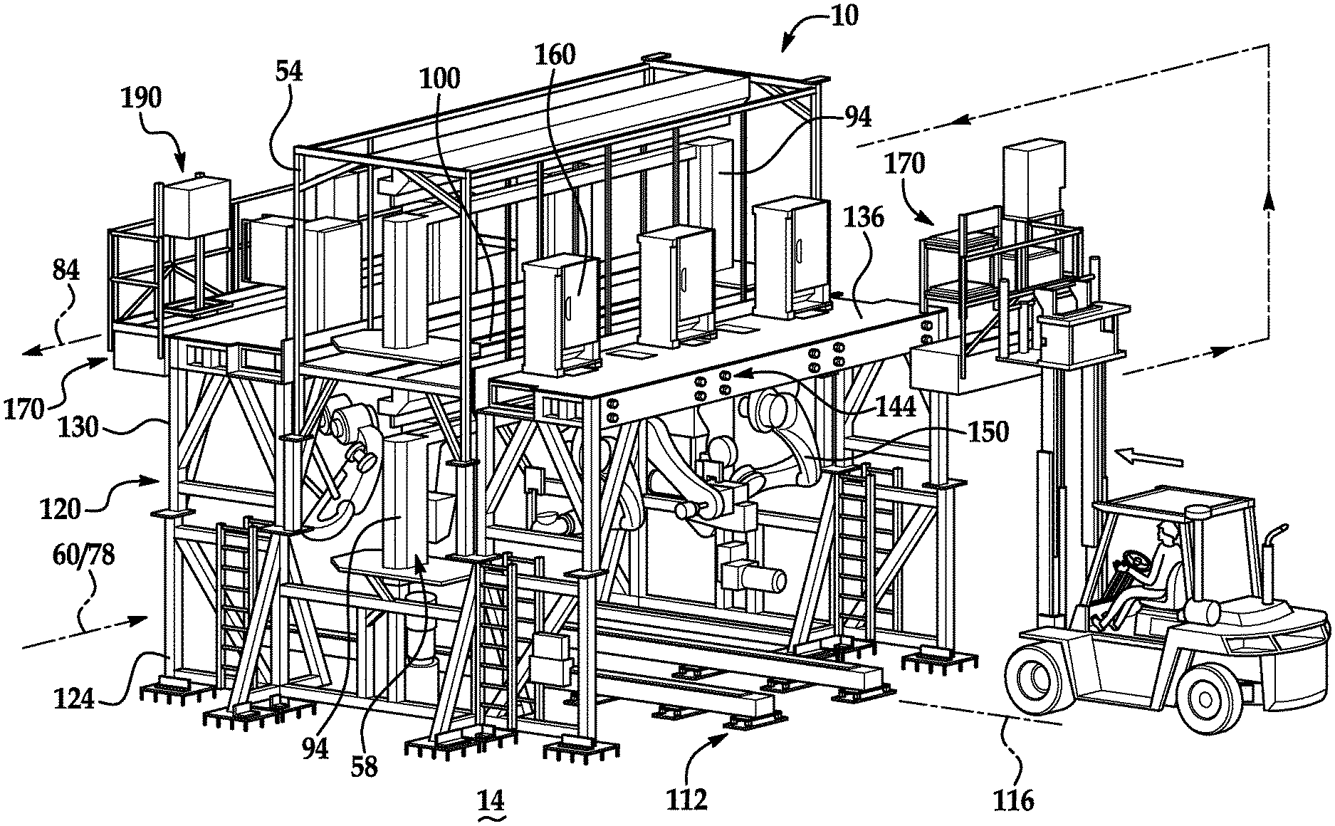
In one example, an AE (application equipment) support pallet is used to support and secure application gear, such as liquid sealant storage tank and distribution pumps above the assembly line, and tools like robots. The modular pallet can be selectively attached to the assembly frame adjacent to or close to the robot or other assembly tools and equipment using the application equipment. It also provides a simple logistics path for conveying consumable materials, sealant, screws, etc. Directly into the assembly cells and robots for application. An example of an invention method is to pre-assemble the pallet device and ship it to the application equipment provider, where the equipment can then be tested and mounted at the supplier before being delivered and installed at the assembly facility. The mounted application equipment’s power, data and material conveyance cables and hoses can be easily connected to coordinating gear at a system integrator facility or directly at the assembly plant. Devices that enable efficient installation, connections and testing at the assembly plant.


In another example, an aspect of the invention provides a modular platform or tray for storing and locating required assembly tools. In one example, an assembly tool platform at floor level is provided. In this example, a modular AT frame or platform is pre-installed with an industrial robot, control panel, and accessory devices. This is coordinated to the existing modular assembly cells infrastructure. The modular support platforms allow the equipment to be tested prior to arriving at the system integrator, assembly plant or factory. They also provide quick and precise positioning within the modular assembly cell infrastructure. This simple, secure, and precise positioning of robots relative to platforms, and of the platform in relation to assembly cells or stations, allows for immediate, predictable, and highly repeatable placement of robots to other assembly cell equipment. The modular AT platform demonstrates secure and predictable positioning for AE devices, such as weld tip dresses for spot welding gun ends effectors attached to robots. This adds to the plug-and-play advantages of installation in the assembly plant.
In the event of a significant maintenance requirement for the application equipment or a model switchover in the assembly plant, modular AE platforms and AT pallets with non-model-specific or model-specific assembly tools and AE devices are simply “unplugged” from the non-model-specific assembly structures. The non-model-specific assembly structures are removed and replaced by the new, refurbished or AE devices and assembly tool equipment that is specific to the new vehicle. This has been tested and commissioned before arriving at the assembly facility.
In another aspect of the invention, a modular fence is used in conjunction with one or several aspects of the modular assembly stations and modular inventive aspects discussed above. The guard fence may include a frame which is cantilevered off the assembly frame. This frame, however, in a preferred aspect does not require a connection to the floor of the assembly plant, as was the case with conventional safety fences. The exemplary fence has an upper and lower position that allows selective access to the assembly tools at the assembly station. In one example, the front panel is placed between the assembly tool and control cabinets of an AT platform. It prevents unauthorised access to the tools, while still allowing access the control cabinets and certain AE devices when the tools are operating.
In a second example, an aspect of the invention is a method for establishing and buying a vehicle assembly line (or another product). In this example, a throughput for an assembly plant is determined and the number individual assembly lines that make up the entire assembly line are also determined. To meet the target for overall throughput, each assembly line’s throughput is calculated. “The required assembly line equipment is divided into infrastructure equipment that is not model-specific and services which are not vehicle-model-specific and vehicle-model-specific systems.
The non-model specific system may include modular frames, AE pallets, AT platforms and conveyors. Non-model specific equipment can be sourced from a single supplier or minimal suppliers. The model-specific assembly equipment for vehicles is competitively priced, preferably by individual assembly lines. The supplier that wins the bid will be responsible for meeting individual line throughput specifications.
The method offers at least advantages such as simultaneous and parallel design of non-model-specific and model-specific equipment, the immediate release of non-model-specific technical details for the assembly lines by the designers, the increased commissioning of equipment at suppliers, and the rapid installation and commissioning at the assembly plants through the connection of modular assembly line components with the application equipment mounted on them. The result is a compressed time to design and build an assembly facility, at a lower cost. Business risk is also more evenly distributed between OEMs and suppliers.
The following description of the invention, which includes examples, will be apparent to those who are skilled in the arts when read together with the accompanying illustrations described below.
Examples and methods of a modular assembly system for vehicles 10 are described and illustrated below. 1-16. “The exemplary assembly systems and devices are useful for high-volume assembling of automotive passenger vehicles. However, there are many other applications in manufacturing and assembling products and vehicles known to those in the art.
Referring to FIG. “Referring to FIG. On a floor of an assembly plant 14, BIW is shown. The example shows a material entry zone 20, a loading and staging or sequencing area 30, and several assembly lines (six in FIG. As shown, assembly lines 40-45 are identified in FIG. Each assembly line includes a vehicle in-process travel path running along each line 40-45.
In the examples, there are two different types of vehicle conveyors that can be used to transport the partially finished vehicle body along the path 60 or through the assembly stations or cell 56. As shown in general on FIG. A pallet 106 supports in general a partially finished vehicle body (not displayed) as shown in FIG. Pallet 106 can be moved from one assembly cell to another by moving it along a path 60 using a rail frame 110 with powered rollers. Comau LLC?s VersaPallet system is an example of a powered system. U.S. Pat. contains additional details. Nos. Nos.


Click here to view the patent on Google Patents.


